Antenna Problems on Little Boy - bomb could not have worked

Pacific War: Tokyo & Japan fire-bombed - 6 & 9 Aug 1945 - Hiroshima & Nagasaki nuke & radiation myths

Antenna Problems on Little Boy - bomb could not have worked   1 of 2

Postby FirstClassSkeptic » 26 Mar 2011 12:32

Here are pictures of two models of Little Boy. The first is in a museum in Japan. I don't know where the second model is located, but it's a popular picture on the net:

Image

Image

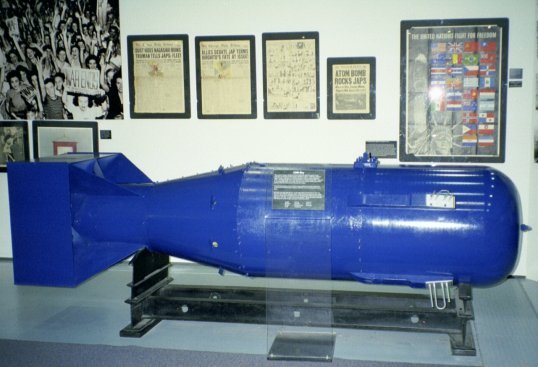
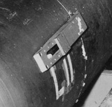
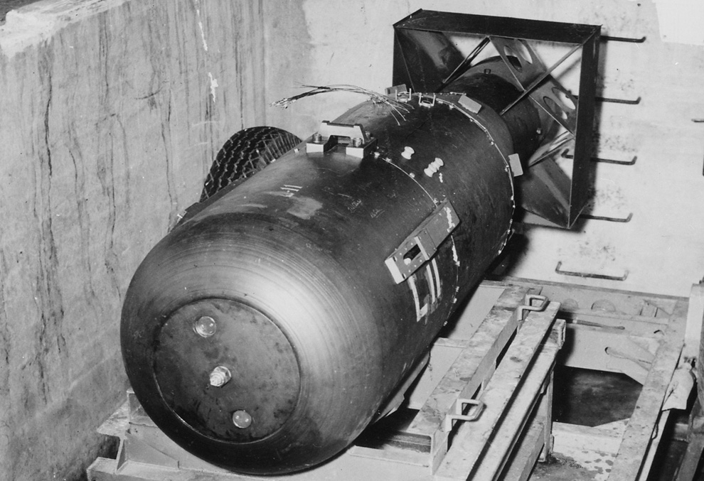
Notice the antenna towards the front of the bomb. The antenna is silvery colored, probably aluminum. It has one loop with two straight rods on each side of the loop. It sets on a rectangle which is also silvery colored. You should be able to see two sets on each model. Presumably, there's another pair behind the model which are hidden from view.

Look at the lengths and spacing of the elements. This is important in an antenna because it determines the frequency and pattern. This antenna that is shown on these models had a patent: 2452073 Compare the relative length and spacing of the antenna on the models with that of the drawings from the patent, shown below.
http://www.google.com/patents/about?id=VotOAAAAEBAJ

Image

Image

Image

UNITED STATES PATENT OFFICE

2,452,073 FOLDED DIPOLE

George William Schivley, Buchtel, and Paul W. Springer, Dayton, Ohio

Application November 17,1944, Serial No. 563,980 1 Claim. (Cl. 250—33.65)

(Granted under the act of March 3, 1883, as amended April 30, 1928; 370 O. G. 757)

The invention described herein may be manufactured and used by or for the Government for governmental purposes, without the payment to us of any royalty thereon. :

The present invention relates to directional antennae.

An object of the invention is to provide a radio antenna for use on the tail of an aircraft in circuit with a warning device, to warn of the presence of another craft in flight within a predetermined range.

A further object is to provide such an antenna which may be applied to various types and sizes of aircraft with a minimum of adjustment.

A further object is to provide such an antenna which is of light weight, highly directional, of controllable wave pattern and range, simple'to manufacture and install and highly efficient in use.

These and other objects will appear throughout the specification and will be pointed out in the claim.

The use of reflected radio wave pulse transmitting and receiving instruments to signal the presence of distant objects is • particularly indicated for use in warning a pilot in flight, particularly a fighter plane pilot, of the presence of an enemy plane just outside firing range directly behind the tail of his plane.

The difficulties of adapting such radio equipment, however, have centered about the control of the emitted and received radio waves so that only reflected waves from planes within the vulnerable area behind the tail and within firing range be indicated. If such warning equipment were actuated by neighboring flight formations, ground signal, or planes beyond firing range, it would inevitably endanger and confuse the pilot. The use of a unidirectional antenna would aid in the direction of the transmitted waves to the rear of the plane. Available antennae, particularly the Yagi type, when applied to the tail fin of a plane, have the disadvantage of requiring, individual tuning for every plane since the thickness of the fins on different aircraft on which the antenna is to be mounted, is subject to considerable variation. The necessity for weight reduction of this auxiliary equipment also limits the usefulness of such antenna because of its low efficiency when bilaterally shrouded.

The present invention utilizes a quarterwave two-section unidirectional dipole antenna of the folded type, one section of which is attached to each side of the airplane vertical fin. These two antenna sections are electrically joined together by a looped phasing and balancing cable section so that regardless of the spacing between the two sections, any variation in width of fins is automatically taken up by the slack in the loop without in any. way affecting the balancing or tuning of the antenna-transmitter-receiver circuit. By such a laterally adjustable construction, the entire problem of antenna installation to various types and sizes of aircraft becomes so simple that installation may be easily accomplished by inexperienced persons unfamiliar with radio circuit balancing or slotted line technique. Once the size of antenna is established by the manufacturer, in balance with the transmitter and receiver, variation in width of tail fin will not affect the range, direction or pattern of the radiated waves, as is the case with rigid Yagi type antennae, in which covering or uncovering of the projecting antenna by the fin surface would change the length and consequently the characteristics of the antenna.

Fig. 1 is a top plan view of the antenna in location with respect to its parasitic reflector, and director;

Fig. 2 is a side elevation on a reduced scale of the antenna shown in Fig. 1, illustrating the normal relationship of antenna and aircraft tail fin;

Fig. 3 is an enlarged schematic diagram of the antenna shown in Fig. 2, illustrating the circuit connections;

Fig. 4 is a cross-sectional illustration of the horizontal field or wave pattern obtainable with the antenna herein described; and

Pig. 5 is a vertical cross-section of the wave pattern horizontally sectioned in Fig. 4

By way of illustration, the preferred embodiment of the invention, as applied to an aircraft tail fin or wing comprises a folded dipole two section antenna, generally referred to as 10 and composed of two U-shaped rods 11 and 12 threaded at their ends for bolting to a pair of assembly plates 13 and 14. Bolted to these plates 13 and it in the plane of the legs of the U-shaped antenna II and 12 and spaced therefrom a pair of parasitic reflector rods 15 and 16 project outwardly parallel with the U-shaped antenna leg sections 11 and 12 and for a greater distance. Parallel with and also in the plane of said antenna sections 11 and 12, a pair of director rods 17 and 18 extend from said assembly plates for a distance less than that of either the parasitic reflectors or the antenna sections. Looped between and electrically connecting one of the adjacent 11 and 12 is a cable 21. This cable is of the coaxial type so that the core conductor 22 may be used to connect the insulated antenna ends 19 and 20 by connectors 23 and the outer conductor 24 may be electrically connected to the grounded assembly plates 13 and 14 by connectors 25. Cable 21 is made an odd multiple of one-half the wave length used in transmission and reception over the antenna. This length of cable has the effect of dividing the current from conductor 26 equally between antennae 11 and 12 and of making the currents in these two antennae equal and in constant, or like, phase in the sense indicated by the arrows in Figure 3. Another length of this coaxial conductor 28 connects the antenna and assembly plates with a radio transmitter and receiver svstem 30.

When so arrayed and in circuit with a pulse transmitter and receiver through coaxial, cable 26; the resultant quarterwave radiated- field or coverage is substantially that of a, cone of 90 degrees in vertical, 60 degrees horizontal at half power with apex at the tail fin; the center- line of the -cone angle extending parallel with the axis of the aircraft. By suitably spacing and balancing the size of :the array the impedance of the array -can be made to match that of any standard coaxial line. The pattern shape can be governed to some extent by suitably spacing the elements. The. characteristic pattern of, the radiated and. reflected waves will remain constant regardless of the space separation (within practical limits) between the opposite faces of the tail fin (and consequently of the antenna sections) which is spanned by the coaxial cable loop 21.

User avatar
FirstClassSkeptic
 
Posts: 671
Joined: 20 Mar 2011 21:19

Re: Antenna Problems on Little Boy

Postby FirstClassSkeptic » 26 Mar 2011 12:45

The antenna had two sections.

As is evident in reading the patent, and looking at the diagrams, the antenna had two parts, or halves, a right hand and a left hand part. One half was to be put on one side of the vertical stabilizer of the plane, and the other half was on the other side.

The antenna was immune to variation in fin thickness, but note that they state, "within practical limits". A fin with a thickness of 28 inches isn't very practical.

Since this antenna was meant to operate in pairs, three APS-13 units would have needed three pairs, and four APS-13 units would have needed four pairs. There are only two pairs, at most, shown on pictures of Little Boy. That would only be enough antennas for two units. Only two APS-13 units are shown in the picture, but the descriptions say, usually, that there were four. Some descriptions say, three units.

Conclusions: 1)There isn't enough antennas on the Little Boy for three or four APS-13 units. There are only enough pairs for two units. 2) The two sections are spaced farther apart then the inventors intended. It was only designed for the thickness of a tail fin on a fighter plane.

The Spacing and Length of the elements are wrong

As stated in the patent, and as is the case with all dipole antennas, the director was to be shorter than the folded dipole element, and the reflector was to be shorter. (Note: The only active element is the dipole, that is the U-shaped part. It's bent into a U shape, so it's called a 'folded dipole'. The other elements, the 'parasitic' elements, which are the straight rods, are only there to guide the radio wave into the dipole. The parasitic elements give the antenna gain, or directivity.

Notice that on the antenna on the models pictured that the three elements are crowded close together. In the second picture, both of the straight rods are shorter than the U-shaped rod. This antenna would have no directivity towards the ground. Also look at the first picture. It does appear to have one rod longer, and the other shorter, than the U shaped rod. But they are still crowded together.

When were the antennas installed?

There are a few pictures that appear all over the net of the bomb in the loading pit.

Here are links to two largish files:

Close up of Little Boy, Boston Globe
http://inapcache.boston.com/universal/s ... _58258.jpg

Little Boy in pit. GWU
http://www.gwu.edu/~nsarchiv/NSAEBB/NSA ... -boy-2.jpg

In both pictures, you can see that the antennas aren't installed. In the second picture, it looks like a rag has been stuffed into the hole.

Close up: Image


According to minute by minute accounts, the bomb was taken to the pit at noon. It was covered with a tarp, and guarded. At 3:00 in the afternoon, it was loaded onto the bomber plane, and at that time William Parsons returned, got into the bombay of the plane, and 'practiced' arming the bomb for two hours. Presumably, at this time, he would have installed the antennas. He had plenty of time. He was the one charged with the task of the final assembly and arming of the bomb while on the plane. Although tediously detailed accounts of the arming proceedure are given in different sources, no mention is made in any story I can find on the net as to when he installed the antennas. No mention is made that he had the antennas with him when he returned to 'practice' the arming while the plane was on the ground. No mention is made that anyone carried the antennas on board the plane.

Of course, just because no account is given doesn't mean it didn't happen. But for something as important as the antennas, which were part of the detonation system, it seems someone would make mention of them. They wouldn't want to get out over the Pacific Ocean, and hear Parsons say, "Dang, I forgot the antennas."
User avatar
FirstClassSkeptic
 
Posts: 671
Joined: 20 Mar 2011 21:19

Re: Antenna Problems on Little Boy

Postby FirstClassSkeptic » 26 Mar 2011 12:56

As with all other subsystems in modern U.S. nuclear weapons, the fuzing mechanisms are complex and backed-up by, and interlocked with, other systems. As an example, even the primitive LITTLE BOY and FAT MAN bombs of 1945 had three separate and interleaved parts to their fuzing systems. The main component was a modified U.S. Army Air Corps APS-13 fighter tail warning radar, nicknamed "Archie."

Source: The Swords of Armageddon: U.S. Nuclear Weapons Development since 1945, Chuck Hansen, September 4, 1995, vol. VIII, pp. 3-45

Memorandum dated July 19, 1943 to Captain W. S. Parsons from R. B. Brode, subject: Fuze Group Program.
By the spring of 1944, the APS-13 "tail warning device" was under study for use as a radar fuse.2 Originally designed to warn a pilot of another aircraft approaching the rear of his plane, the "Archie" had an effective range of about 2,000 to 2,500 feet.3

The arming and firing sequence for the first two atomic bombs was (1) 15 seconds after release, when the weapon had fallen 3,600 feet, the timer switches closed part of the firing circuit; (2) at an altitude of 7,000 feet, the barometric switch closed another part of the firing circuit and allowed electrical current from batteries in the bomb to charge a number of capacitors and turn on the radar fuses; (3) at an altitude of about 1,800 feet, radar signals emanating from the "Archies" and reflecting from the ground completed the last part of the firing circuit and triggered the detonation signal.
In the MK I LITTLE BOY, the firing signal went directly to the explosive primer that ignited the propellant to fire the uranium-235 projectile into the "target" uranium-235 assembly in the nose of the casing.


The above was take from the web page PART V: ARMING & FUZING: TECHNIQUES & EQUIPMENT.
http://cryptome.org/nuke-fuze.htm

http://planerpandemonium.webs.com/littl ... ation.html
User avatar
FirstClassSkeptic
 
Posts: 671
Joined: 20 Mar 2011 21:19

Re: Antenna Problems on Little Boy

Postby TVOW » 26 Mar 2011 14:06

The model in the British war museum when I went about a year ago was at least twice the size of the ones in these photo’s
TVOW
 
Posts: 59
Joined: 21 Mar 2011 21:30

Re: Antenna Problems on Little Boy

Postby rerevisionist » 26 Mar 2011 14:30

Congratulations on a brilliant and detailed piece of research.
User avatar
rerevisionist
Site Admin
 
Posts: 1056
Joined: 18 Mar 2011 11:40

Re: Antenna Problems on Little Boy

Postby NUKELIES » 26 Mar 2011 15:35

Yes thanks Skeptic for this valuable contribution. We need more real science everybody!
User avatar
NUKELIES
Site Admin
 
Posts: 302
Joined: 17 Mar 2011 15:53
Location: UK/USA

Re: Antenna Problems on Little Boy

Postby FirstClassSkeptic » 26 Mar 2011 18:49

TVOW wrote:The model in the British war museum when I went about a year ago was at least twice the size of the ones in these photo’s


Maybe that's why the antenna looks crowded? Maybe it's a full size antenna on a shorter bomb?

The original was ten or twelve feet long. These models look about ten feet long to me. They look the right scale when compared to other pictures of the 'real' Little Boy.
User avatar
FirstClassSkeptic
 
Posts: 671
Joined: 20 Mar 2011 21:19

Re: Antenna Problems on Little Boy

Postby FirstClassSkeptic » 26 Mar 2011 18:55

Here's a side note:
In one of the famous pictures of Little Boy, there are two men standing in front of it, the cover is off of the bomb revealing the internals, and one is painting L11 on the side of the bomb.

Now look at this picture, which I previously posted:
Image

Does that look like L11 has been painted on? It looks like tape, or a decal to me.

There were two Little Boys delivered to Tinian; one a 'dummy' and the other one 'real'. But these two pictures are supposed to be of the real one. At least, that is how they caption them.

So what do you think?
User avatar
FirstClassSkeptic
 
Posts: 671
Joined: 20 Mar 2011 21:19

Re: Antenna Problems on Little Boy

Postby NUKELIES » 27 Mar 2011 02:08

Regarding L11 - It does look like it could be tape or it could be a stencil. I looked close but can't tell.
User avatar
NUKELIES
Site Admin
 
Posts: 302
Joined: 17 Mar 2011 15:53
Location: UK/USA

Re: Antenna Problems on Little Boy

Postby FirstClassSkeptic » 27 Mar 2011 12:03

Image

The description this picture, from the page on which it appears:
This is an actual size model of Little Boy, the A-bomb dropped on Hiroshima. It’s only 3 meters long. (The fission material was uranium 235. It’s said that a little bit over 50kg of them were loaded in Little Boy (80% of 64kg).)


http://joumon-juku.com/23/English/09_e.html
User avatar
FirstClassSkeptic
 
Posts: 671
Joined: 20 Mar 2011 21:19

Re: Antenna Problems on Little Boy

Postby FirstClassSkeptic » 27 Apr 2011 06:40

Very interesting interview with Morris Jeppson:

Mainichi: What kind of role did you take during the Hiroshima mission?

J: Well, I was trained for that role -- at Harvard and MIT in electronics, (and) at MIT in radar engineering -- and there were four small radars built into these bombs. There was an antenna for one of them, and there were four of them. They were very simple -- all they detected was firing an electronic signal to the ground which bounced back up and measured the time delay, and that measured the height of this bomb as it was falling above ground.

So my role -- six of us ended up from the Harvard and MIT electronic schools, Air Force schools. We were hired by Los Alamos to work with the Air Force on the fusing -- the radar fusing and all other stuff that was built in the bomb.

I was a weapon test officer and we worked with Los Alamos in the Air Force. I was in the Air Force during the evolution of the electronics fusing system of the bomb. And then I was chosen to fly the Hiroshima mission and it was still experimental, so I was to test the electronics on the bomb during the flight to Hiroshima. If there was a problem with the electronics, I reported the problem to this man (and) he told the pilot of the airplane to take the bomb back. In fact, I was instructed to tell him to take the bomb back to (the Pacific island of) Tinian if it wasn't working right.


Jeppson says the radar units 'measured the time delay'. The units were APS-13 units, and there was no circuitry in them to measure time delay. If Jeppson was a physicist and an electronics expert, as he claims, he should know this. With a radio signal traveling at the speed of light, and the bomb being only 1900 feet from the ground at detonation, that would be a 3800 foot round trip, and that would be a very small interval to measure.

3800 ft / 983571056ft/sec = 3.86 X 10^-6 seconds.

He says there were four units, and an antenna for one of them. He must have meant to say, for each one of them. Well, there was an antenna, but only half of an antenna pair.
User avatar
FirstClassSkeptic
 
Posts: 671
Joined: 20 Mar 2011 21:19

Re: Antenna Problems on Little Boy

Postby FirstClassSkeptic » 27 Apr 2011 06:54

From the same interview with jeppson:
Mainichi: How about the bombardier?

J: (Thomas) Ferebee? He didn't know. He knew it had to be a very powerful bomb; otherwise he wouldn't have detonated it up high above the ground. If it had been detonated -- let's say the plane was flying at a low altitude like all of these hundreds of B-29s -- it would have destroyed the B-29 because they normally flew at six or seven thousand feet. This one flew at 30,000 feet. So the blast was like a shockwave -- it was a shockwave, but it didn't damage the airplane.


http://zeroempty000.blogspot.com/2009/0 ... ember.html

After explaining how the electronics detonated the bomb, he later says Ferebee detonated it. What did Ferebee have to do with how high the bomb detonated? Well, he couldn't have had anything to do with it.
User avatar
FirstClassSkeptic
 
Posts: 671
Joined: 20 Mar 2011 21:19

Return to WW2 Japan - Proofs that Hiroshima & Nagasaki were not A-Bombed


Who is online

Users browsing this forum: No registered users and 1 guest